Design Scheme for Primary Reverse Osmosis (RO) System in Ultrapure Water Engineering
Design Scheme for Primary Reverse Osmosis (RO) System in Ultrapure Water Engineering
1.0 Design Basis and Objectives
-
System Positioning:Serves as the primary desalination barrierin the ultrapure water system, providing qualified feed water for subsequent core polishing systems (secondary RO, EDI, mixed bed).
-
Source Water:Effluent from pretreatment processes (multi-media filtration, activated carbon filtration, softening, etc.).
-
Feed Water Quality Requirements:
-
SDI₁₅ < 4
-
Turbidity < 0.5 NTU
-
Residual Chlorine < 0.05 mg/L
-
Hardness (as CaCO₃) < 50 mg/L
-
-
-
Product Water Objectives:
-
Salt Rejection:≥ 97% (typically achievable: 98-99%)
-
Recovery Rate:70 - 75% (conservative design for system safety)
-
Product Water Quality:Conductivity < 30 µS/cm (providing ideal feed for secondary RO)
-
2.0 Process Flow Design for the Primary RO System
The primary RO system is not merely a simple filtration unit but a complete system integrating high-pressure pumping, precision filtration, chemical dosing, and energy recovery. Its core design logic is as follows:
flowchart TD
    A[Pretreated Water] --> B[RO Feed Tank]
    B --> C[RO Feed Pump]
    C --> D[Antiscalant Dosing]
    D --> E[Reducing Agent Dosing<br>Optional]
    E --> F[Cartridge Filter<br>5µm]
    F --> G[RO High-Pressure Pump]
    G --> H[Primary RO Membrane Array]
    H -- Concentrate --> I[Energy Recovery Device<br>Optional]
    I --> J[Concentrate Discharge]
    H -- Permeate --> K[Primary RO Permeate Tank]
    K --> L[Secondary RO System]

subgraph Support[Support Systems]
    M[CIP Cleaning System] --> H
    N[Instrumentation & Control System] --> B & G & H
end

Step-by-Step Process Explanation:
-
Feed Water and Stabilization:
-
RO Feed Tank:Buffers fluctuations in pretreated water output, providing a stable water supply for the RO system. The tank is equipped with a vent filter to prevent contaminant ingress.
-
RO Feed Pump:Provides stable feed pressure for the subsequent cartridge filter and high-pressure pump.
-
-
Chemical Dosing (Key to Membrane Protection):
-
Antiscalant Dosing:Mandatory. Effectively inhibits scaling of sparingly soluble salts (e.g., CaCO₃, CaSO₄, SiO₂) on the membrane surface, allowing the system to operate at higher recovery rates.
-
Reducing Agent Dosing (Optional):Acts as a safety backup if the pretreatment activated carbon filter fails or if residual chlorine fluctuates. Sodium bisulfite (NaHSO₃) is dosed to completely eliminate residual chlorine, protecting the RO membrane from oxidative damage.
-
Non-Oxidizing Biocide (Intermittent Dosing):Periodically dosed as a shock treatment to control microbial growth.
-
-
Final Cartridge Filtration:
-
5µm Cartridge Filter:Serves as the final physical barrier, absolutely preventing any particulates from entering the high-pressure pump and RO membrane elements, avoiding abrasion of the membrane surface.
-
-
High-Pressure Pumping and Desalination:
-
RO High-Pressure Pump:Provides the power required for the RO membrane to overcome the osmotic pressure. Typically uses a multi-stage centrifugal pumpwith Variable Frequency Drive (VFD) control to adapt to system start/stop and flow variations.
-
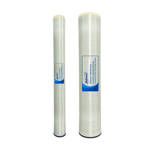
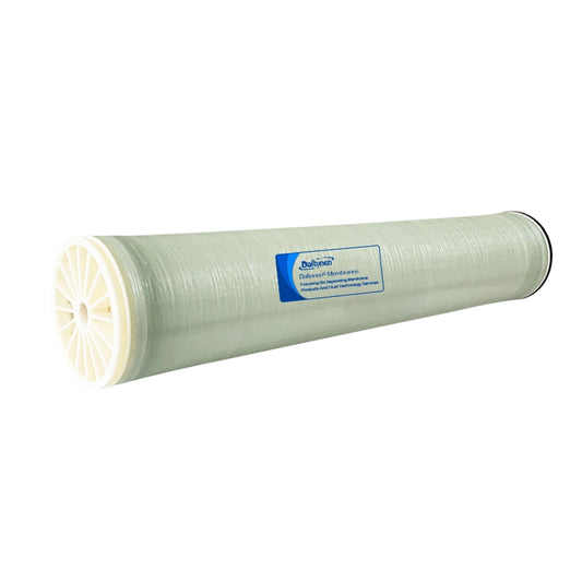
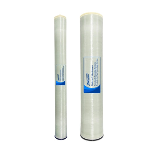
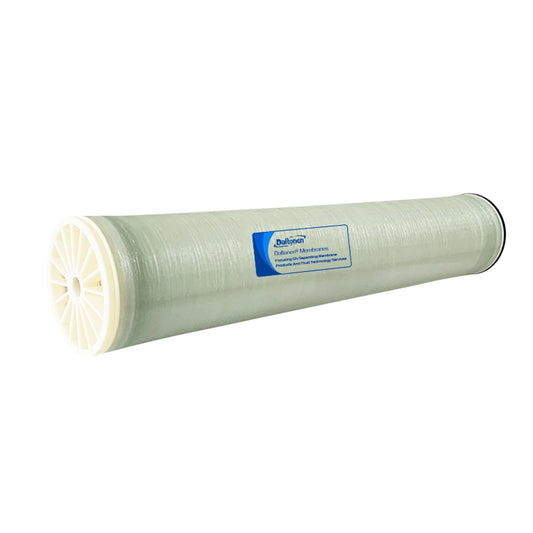
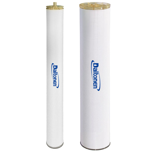
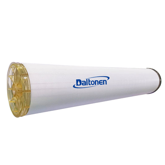
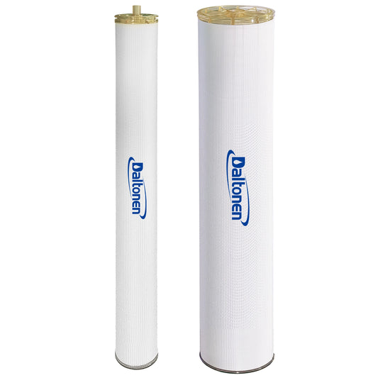
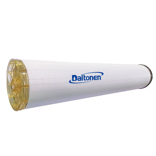
Primary RO Membrane Array:The core desalination unit. Typically uses spiral-wound polyamide composite membranes. The membrane elements are arranged in a single-stage, two-passconfiguration (e.g., 4:2 or 3:2 array) to balance flux and recovery. Under high pressure (~1.0 - 1.5 MPa), water molecules permeate through the membrane as product water, while ions, organics, microorganisms, etc., are rejected, forming the concentrate stream.
-
-
Concentrate Management and Energy Recovery (Key to Energy Saving):
-
Energy Recovery Device (Optional):For large-scale systems, the concentrate still possesses high pressure. Installing an energy recovery device (e.g., PX pressure exchanger) can recover ~95% of the concentrate pressure and transfer it to the feed line, significantly reducing the energy consumption of the high-pressure pump (can reduce by up to 30-40%).
-
Concentrate Discharge:Part of the concentrate can be recycled to the RO feed to adjust the recovery rate; the remainder is discharged or reused for pretreatment backwashing.
-
-
Cleaning-In-Place (CIP) System:
-
Necessity:Membrane fouling is inevitable. A CIP system is essential for periodic or on-demand cleaning of the membrane elements to restore their performance.
-
Components:Includes a cleaning tank, cleaning pump, heater, and piping. Common cleaning agents are acidic (e.g., citric acid, HCl) for inorganic scale removal and alkaline (e.g., NaOH) for organic fouling and biofouling removal.
-
3.0 Core Design Parameters and Equipment Selection
|
Parameter / Equipment |
Design Specifications and Selection Criteria |
|---|---|
|
Membrane Element Selection |
Select low-energy, high-rejection, fouling-resistant brackish water membrane elements (e.g., DOW FILMTEC™ BW30-400/34i, Hydranautics ESPA2). |
|
Membrane Vessels |
Fiber Reinforced Plastic (FRP) construction, pressure rating meets design requirements. Typically holds 6-7 membrane elements per vessel. |
|
Array Configuration |
Single-stage, two-passarray (e.g., 4-2, 3-2). Ensures reasonable cross-flow velocity across each stage's membrane surface, reducing fouling. |
|
Design Flux |
18 - 25 LMH(Liters per square meter per hour). Conservative flux design is key to long membrane life and low cleaning frequency. |
|
Operating Pressure |
1.0 - 1.5 MPa(depending on feed salinity and temperature). |
|
Recovery Rate |
70 - 75%. Conservative recovery rate setting is the most important measure to prevent membrane scaling. |
|
High-Pressure Pump |
316 Stainless Steel multi-stage centrifugal high-pressure pump with VFD control. Flow and pressure must meet the requirements of the first membrane pass. |
|
Instrumentation & Control |
Essential Online Instruments:Inlet/Permeate/Concentrate pressure gauges, Inlet/Permeate conductivity meters, Flow meters (feed, permeate, concentrate). Control System:PLC automatic control, featuring automatic start/stop, low-pressure protection, high/low-pressure alarms, automatic flushing, etc. |
4.0 System Control and Maintenance Strategy
-
Automatic Flushing:Automatically flushes the membrane surface with low-pressure water (typically product water) during system shutdown or after a period of operation to displace the high-concentration brine and mitigate fouling.
-
Data Logging and Early Warning:The system should continuously record normalized permeate flow, salt rejection, and differential pressure (ΔP). When these parameters deviate from baseline values by more than 15%, the system should alarm and prompt for chemical cleaning.
-
Integrity Testing:Perform regular membrane integrity tests (e.g., pressure decay test) to ensure no membrane element is damaged, guaranteeing product water quality.
5.0 Scheme Summary
The core of this primary RO system design scheme lies in its robustness and reliability.
-
Multiple Protections:Multiple measures—"antiscalant + cartridge filtration + conservative flux/recovery rate"—minimize the risk of membrane fouling to the greatest extent.
-
Intelligent Operation:Automated control and online monitoring enable stable, efficient system operation and provide scientific guidance for maintenance.
-
Central Role:As the "heart" of ultrapure water production, its stable product water is the foundation for the long-term safe operation of all subsequent polishing systems.
This scheme provides a comprehensive professional design framework for the primary RO system in ultrapure water projects. Precise calculations based on specific water quality reports are necessary for actual engineering applications.
